


This article is part of CAN Bus Embedded Development, my growing online book about practical CAN Bus hardware, software, and embedded system development.
View the complete Table of Contents →
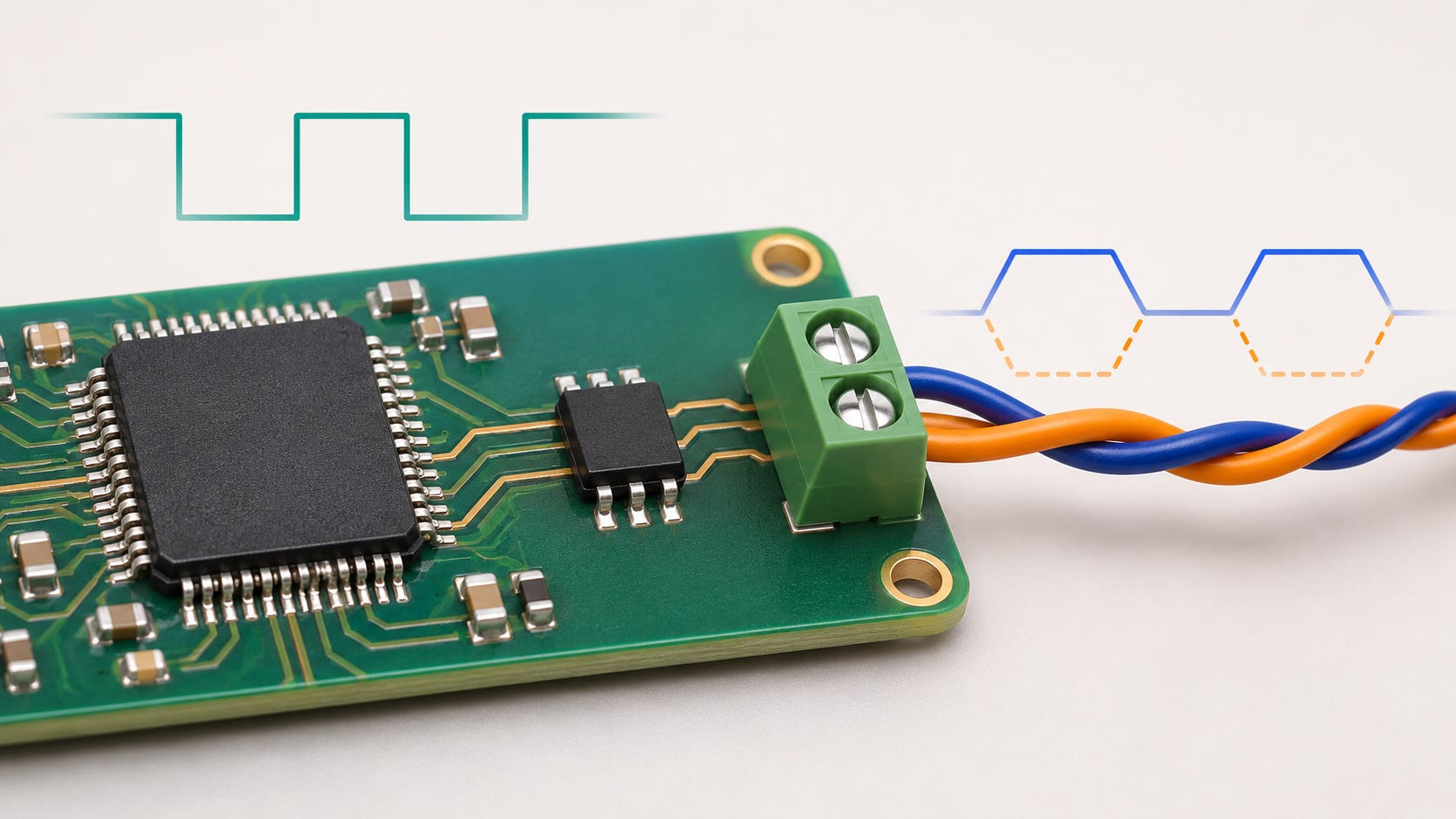
A CAN controller handles the transmission and reception of CAN frames, but to connect it to a high-speed CAN bus, you still need a CAN transceiver. The controller handles the protocol, including frame formatting, arbitration, and error detection. The transceiver provides the electrical interface to the cable. If your development board or module already includes a transceiver, that circuit is already in place.
From logic levels to bus voltages
A typical CAN controller communicates with the transceiver over two single-ended digital signals. The controller sends bits to the transceiver’s TXD input. The transceiver monitors the bus and reports its state back to the controller through RXD. These pins operate at the logic levels specified in the datasheets, commonly 3.3 V or 5 V. When selecting a transceiver, check that its TXD and RXD levels are compatible with your microcontroller. Some transceivers provide a separate VIO pin so the digital interface can use a different supply voltage from the bus driver.
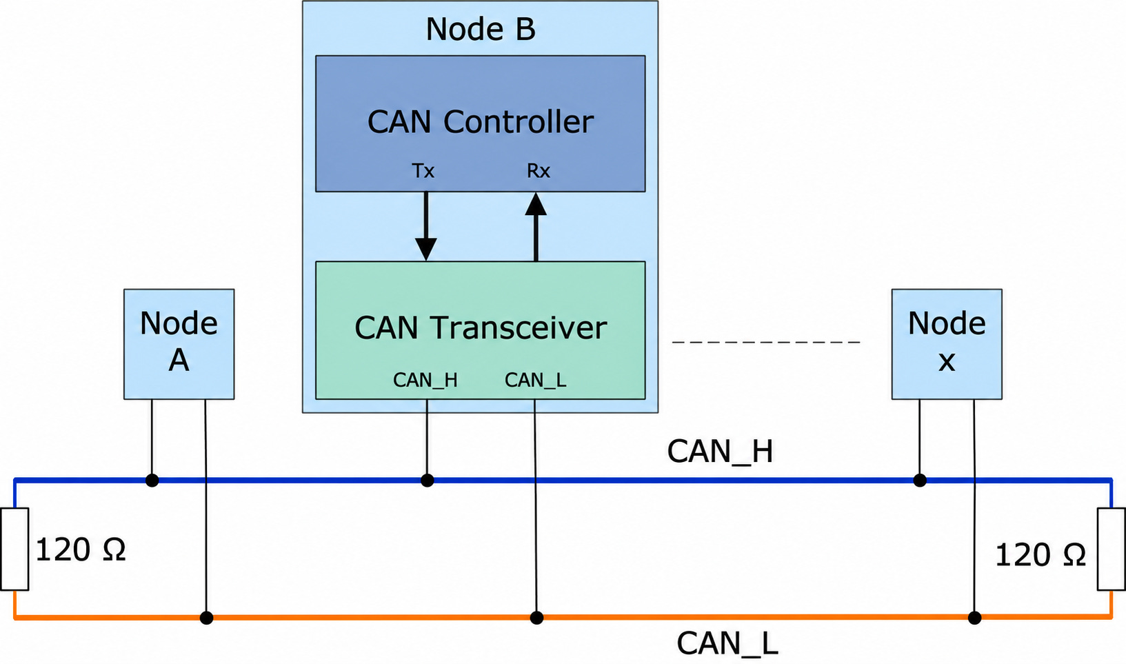
On the cable side, the transceiver drives and senses CAN_H and CAN_L. The receiver determines the bus state from the differential voltage, Vdiff = V(CAN_H) − V(CAN_L). The following values are typical for a conventional 5 V high-speed CAN transceiver on a properly terminated bus.

The names CAN_H and CAN_L describe how the two wires move when a transceiver drives a dominant bit. CAN_H rises, and CAN_L falls. In the recessive state, the wires sit at nearly the same voltage. The 2 V and 0 V figures are nominal examples. A receiver uses specified voltage thresholds to distinguish the two states.
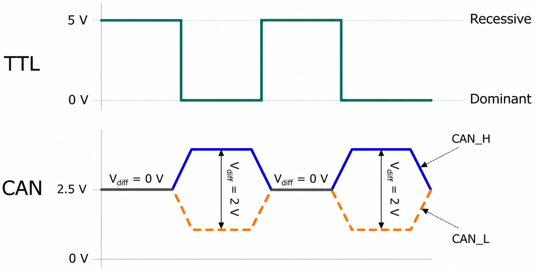
The common-mode voltage is the average of the two wire voltages relative to the measurement ground. In both rows of the table, it is about 2.5 V. A ground offset between two nodes can shift both voltages as seen by the receiving node while leaving their difference largely intact. The receiver still needs to operate within its specified common-mode range.
Why differential signaling helps
Suppose interference raises CAN_H and CAN_L by 0.3 V at the same instant. Both voltages change relative to ground, but their difference stays the same. A twisted pair helps both wires pick up similar amounts of interference, allowing the receiver to reject much of that common-mode noise. If the interference couples more strongly to one wire, part of it appears as differential noise and can affect reception.
How the transceiver makes arbitration possible
A transceiver actively drives a dominant bit and releases that differential drive for a recessive bit. If one node sends recessive while another drives dominant, both see dominant on the bus. During arbitration, each CAN controller compares the bit it sends with the bus state reported through RXD. A controller that sends recessive and reads back dominant yields, allowing the higher-priority frame to continue.
Several nodes can also drive the same dominant bit at once. Their combined drive can produce a somewhat larger differential voltage than a single transmitter produces. If you’re looking at a scope trace, a taller dominant pulse during arbitration can therefore be a normal part of CAN communication.
Connecting the transceiver
On the schematic, connect the controller’s transmit output to TXD and its receive input to RXD. Connect the transceiver’s CAN_H and CAN_L pins to the bus pair. On a conventional high-speed CAN bus, place one 120 Ω termination across the pair at each physical end of the backbone. A node that connects along the backbone typically leaves its termination disabled.
When choosing a transceiver, match its logic interface to the microcontroller and check that it supports your network’s bit rates, including the data-phase rate if you’re using CAN FD. The transceiver drives the cable, reads the shared bus state, and gives the controller the feedback it needs to participate in arbitration.

Embedded Systems Programming with C: Writing Code for Microcontrollers
Embedded Systems Programming with C: Writing Code for Microcontrollers is a practical guide for experienced programmers who want to write efficient, reliable firmware. On a microcontroller, software must work within the limits of the hardware. Memory is finite, timing matters, and even small design choices can affect how much power a device consumes. This book explains how those constraints shape the C code behind products ranging from automotive electronics to consumer devices.
The book connects advanced C programming techniques with microcontroller architecture, real-time operating systems, and power management. Examples and case studies show how to apply these concepts to practical decisions, from organizing code around timing requirements to balancing responsiveness with power consumption.
The book also explores how IoT connectivity and embedded AI introduce new demands on firmware. Throughout, the emphasis is on making sound design decisions about security, power efficiency, and reliability within the resources your hardware provides. More information…