


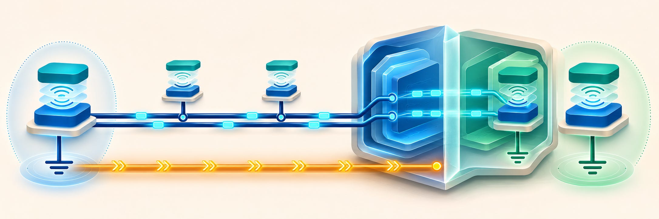
A CAN Bus network can run reliably for years without galvanic isolation. A short bench setup with several boards powered by the same supply is a good example. Now imagine connecting a controller in one cabinet to a drive in another, with each cabinet powered and grounded separately. Even if the wiring and termination are correct, the two cabinets can sit at different ground potentials. That difference is where galvanic isolation earns its place.
Why differential signaling only goes so far
A CAN transceiver reads the voltage difference between CAN_H and CAN_L. If both wires shift by the same amount relative to the receiving node’s ground, their difference stays the same. The receiver can still read the signal as long as the shift stays within its common-mode operating range. Once that range is exceeded, a perfectly recognizable differential signal on an oscilloscope can still produce errors at the receiving node.
A ground loop forms when there is more than one conductive path between ground points. For example, two cabinets may already be connected through the building’s protective earth, and a CAN cable’s ground conductor can provide a second path. A voltage difference between the cabinets can drive current through that loop. The resulting voltage drops and noise can cause intermittent CAN errors or take the network offline. If a large enough fault current flows through the cable, connectors, or PCB traces, or if voltages exceed the transceivers’ limits, the result can be permanent hardware damage.
When isolation is worth adding
Galvanic isolation lets CAN transmit and receive signals cross a barrier while keeping the local controller ground electrically separate from the bus-side ground. The bus-side transceiver also needs a power source referenced to the bus side, such as an isolated DC-to-DC converter or a suitable bus-side supply. A direct ground connection across the barrier would recreate the path the isolation was intended to break.
Isolation is optional in a CAN design where the ground differences and noise stay comfortably within the transceivers’ limits. I recommend it for long runs between separately powered or grounded equipment, especially when the ground offset is hard to predict. Cable length is a clue. A short cable between two machines with noisy or separately grounded supplies can make a stronger case for isolation than a longer cable within a well-controlled grounding system.
Does isolation protect against overvoltage?
It can help contain the damage, depending on where the voltage appears. A difference between the bus-side ground and the controller ground stresses the isolation barrier. A short from CAN_H or CAN_L to a power supply stresses the bus-side transceiver. Those are two different electrical stresses with separate ratings. For example, the TI ISO1042 specifies a ±30 V common-mode operating range, ±70 V DC bus-fault protection, and a 5,000 V RMS isolation withstand test for one minute. The last figure describes a test across the isolation barrier. The CAN pins have their own, much lower limits.
If a fault destroys the bus-side transceiver while the barrier holds, the microcontroller and the rest of the local electronics may survive. That is a real benefit. Whether they survive depends on the severity of the fault and any other paths it can take through the equipment. The isolation barrier is designed to withstand specified electrical stress. The idea that it will reliably sacrifice itself and save every other component promises more than the ratings support.
What happens when the isolated CAN port fails?
If the failure takes out the node’s only CAN interface, that node is out of service on the network, even if its processor keeps running. The rest of the network may continue communicating if the failed port leaves the bus electrically undisturbed. If it shorts the lines or holds the bus dominant, one failed port can stop communication for every node on that segment.
Repairability depends on the hardware. A sealed module will usually be replaced in the field. On a serviceable board, a technician may be able to replace a damaged isolator or transceiver and restore communication if the damage was confined to that part. So when I say that a node with a failed CAN interface is effectively dead, I mean it is dead as a participant on the network. Whether the board can be repaired is a separate question.