


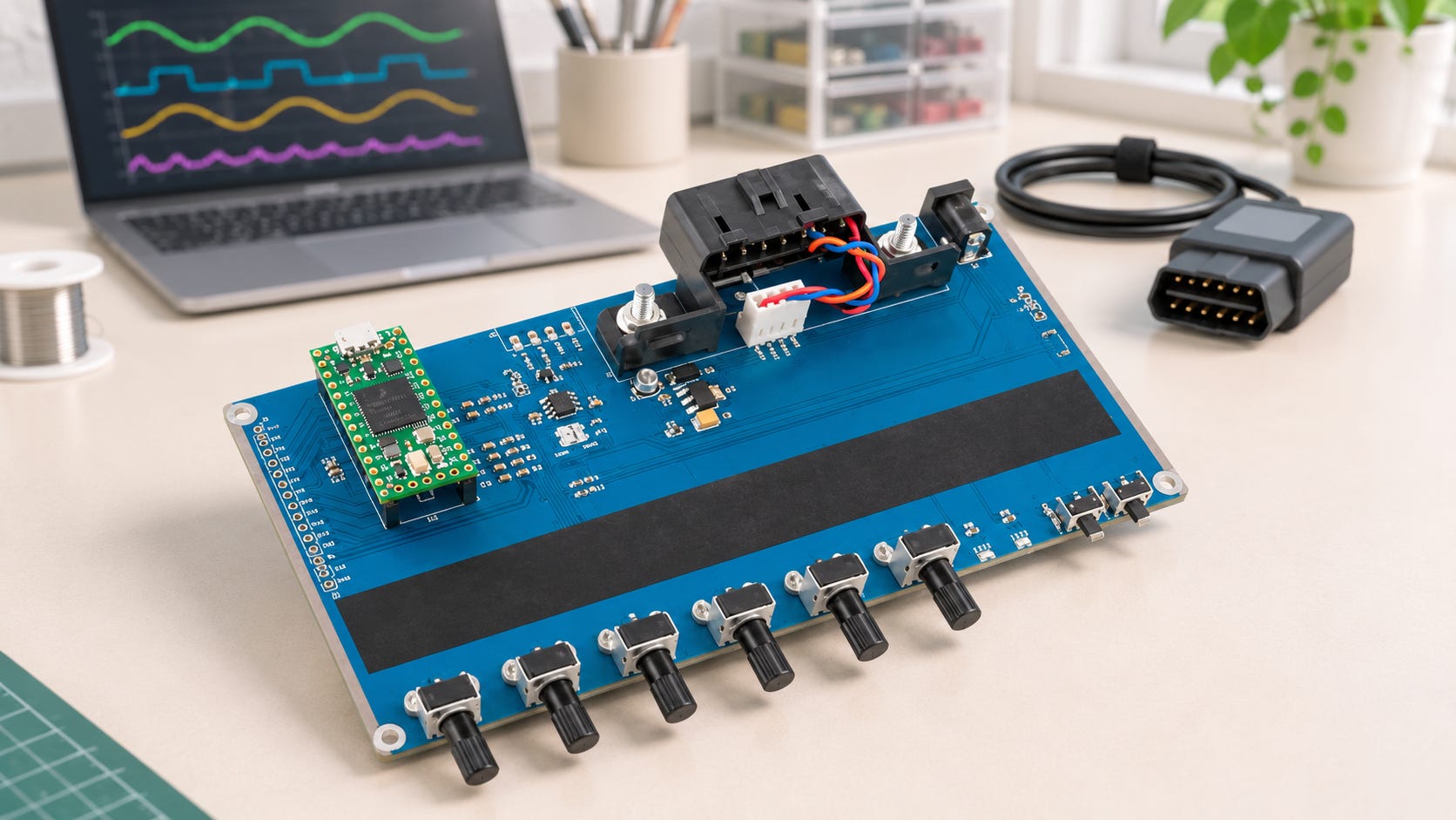
Suppose you’re writing a program that reads engine RPM through an OBD-II adapter. You plug it into a car, start the engine, and your program displays 800 RPM. That sounds plausible. But how do you know your program will decode the next reading correctly, or that your display will update when the value changes? On the workbench, you can turn a knob, watch the value change, and repeat the same test after every change to your code.

The Teensy 4.0 OBD-II CAN Bus ECU Simulator from Copperhill Technologies, plays the role of the vehicle’s electronic control unit (ECU). Your scan tool or OBD-II adapter plugs into the simulator’s diagnostic connector and sends requests as it would in a vehicle. The simulator comes with the Teensy 4.0 installed and programmed, and a 12 VDC power adapter is included. Six knobs let you vary simulated readings such as engine speed, vehicle speed, and coolant temperature while your application is running.
Start with engine RPM
Engine speed is a good first test because a single request takes you through the whole process. Your application sends a Mode 01 request for PID 0C, the parameter ID for engine RPM. The ECU responds with two data bytes. If those bytes are 0C 80 in hexadecimal, the engine speed is 800 RPM. The calculation is (256 × 12 + 128) ÷ 4.
Now turn the RPM knob while your application polls for new readings. If you have a CAN monitor on the bench, capture the response and compare the decoded value with what your application displays. If the response bytes change and the display stays at 800 RPM, you know the new value reached the bus. You can then trace what happens between the adapter and the display. If the display changes but shows four times the expected value, check whether your decoder applied the final division by four.
Move on to freeze frames and trouble codes
The product documentation lists three diagnostic modes. Mode 01 reads current data. Mode 02 reads freeze-frame data, a snapshot of operating conditions captured when a fault was detected. Mode 03 retrieves stored diagnostic trouble codes (DTCs). That distinction matters in a scan tool. A coolant temperature shown under live data answers a different question from the temperature captured when the fault occurred.
The simulator uses the ISO 15765-4 CAN configuration with 11-bit identifiers at 500 kbit/s. Set your interface to match if you’re working directly with CAN frames. SK Pang also provides an Arduino demo sketch, so you can follow the request and response logic in the source code or adapt it to add a parameter your application needs.
If you’re new to OBD-II, start by getting one RPM reading you can verify by hand. Then change the simulated speed and check that your application follows it. Once that works, you have a bench setup you can return to every time you add a parameter, change the decoder, or troubleshoot a display that seems stuck. More information…

Embedded Systems Programming with C: Writing Code for Microcontrollers
Embedded Systems Programming with C: Writing Code for Microcontrollers is a practical guide for experienced programmers who want to write efficient, reliable firmware. On a microcontroller, software must work within the limits of the hardware. Memory is finite, timing matters, and even small design choices can affect how much power a device consumes. This book explains how those constraints shape the C code behind products ranging from automotive electronics to consumer devices.
The book connects advanced C programming techniques with microcontroller architecture, real-time operating systems, and power management. Examples and case studies show how to apply these concepts to practical decisions, from organizing code around timing requirements to balancing responsiveness with power consumption.
The book also explores how IoT connectivity and embedded AI introduce new demands on firmware. Throughout, the emphasis is on making sound design decisions about security, power efficiency, and reliability within the resources your hardware provides. More information…