


This article is part of CAN Bus Embedded Development, my growing online book about practical CAN Bus hardware, software, and embedded system development.
View the complete Table of Contents →
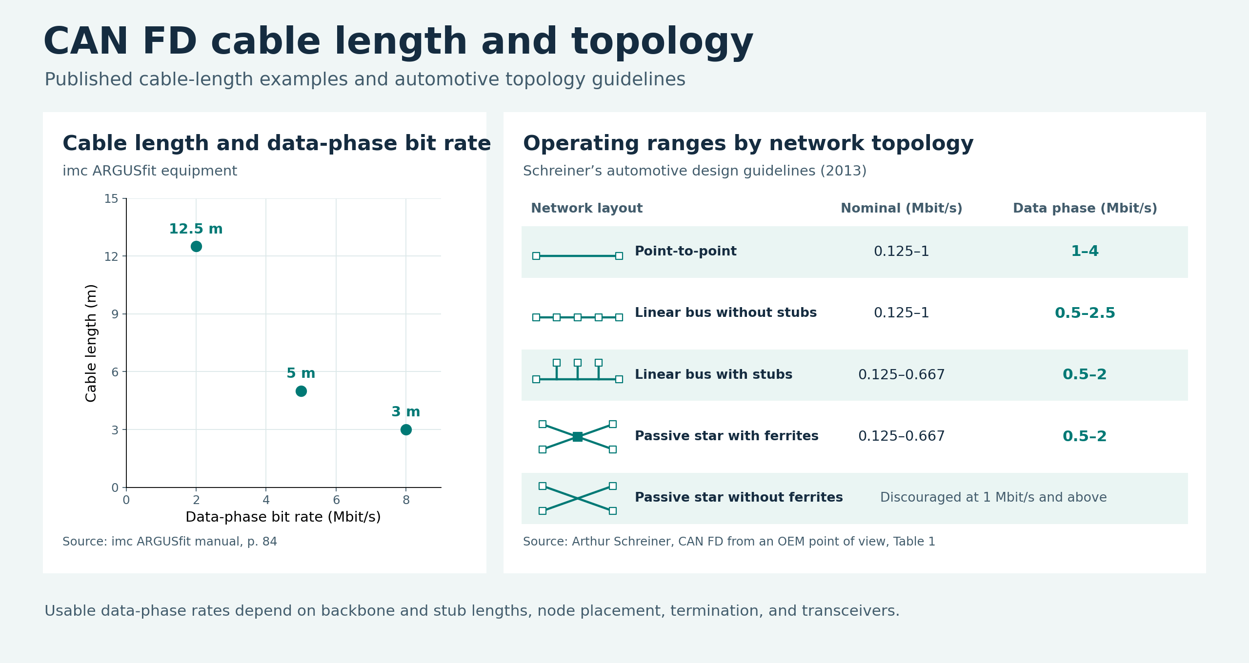
One of the first questions in designing a CAN network is how far the cable can run. The usual answer starts with the bit rate. A slower bit rate gives the signal more time to travel between nodes, which generally allows a longer bus. That relationship is easy to illustrate for Classical CAN. With CAN FD, the picture changes significantly. The faster data phase places tighter demands on the wiring, and the layout of the network can become just as important as the distance between its endpoints.
Practical guidance on CAN FD network design can be hard to find in one place. One source may list cable lengths for a particular device, while another explains how stubs, termination, and transceivers affect the usable data-phase bit rate. To judge whether a published figure applies to your network, you need to know the wiring layout and hardware behind it. For a more detailed discussion of these design factors, see the references at the end of this post.
