


This article is part of CAN Bus Embedded Development, my growing online book about practical CAN Bus hardware, software, and embedded system development.
View the complete Table of Contents →
Maximum Reliability
The Controller Area Network (CAN) is most closely associated with the automobile. For decades, CAN has provided the communication backbone connecting electronic control units for engines, transmissions, braking systems, body electronics, instrumentation, and countless other functions.
But CAN did not remain confined to vehicles.
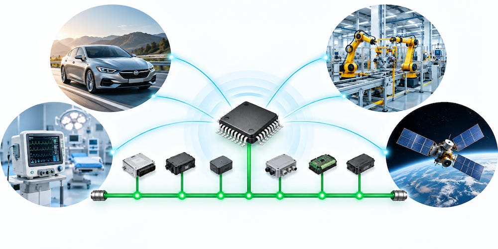
Its combination of robustness, deterministic behavior, sophisticated error detection, and fault confinement made it attractive wherever communication must continue to work reliably in electrically noisy and demanding environments. Today, CAN can be found in industrial automation, mobile machinery, medical equipment, transportation systems, aerospace applications, and even satellites.
That widespread adoption is no accident. Reliability was one of the fundamental design goals of Classical CAN.
More Than Error Detection
Many communication protocols can detect corrupted data. CAN goes considerably further.
A CAN controller continuously monitors communication while a message is being transmitted. Errors can therefore often be detected immediately, rather than waiting until an entire message has been received and subsequently rejected.
Classical CAN uses several complementary error-detection mechanisms:
Bit Monitoring
A transmitting CAN node also monitors the bus while it transmits.
Except for defined situations such as arbitration and acknowledgment, the bit observed on the bus must correspond to the bit the node attempted to transmit. If they differ, the controller detects a bit error.
This is particularly powerful because the transmitter is effectively checking its own transmission in real time.
Bit Stuffing
CAN uses bit stuffing to maintain synchronization. After five consecutive bits of identical polarity, the transmitter inserts a bit of the opposite polarity.
Every receiving node knows this rule. If the expected stuff bit is missing or has the wrong value, the receiver detects a stuff error.
Bit stuffing therefore serves two purposes: maintaining synchronization and providing another mechanism for detecting corrupted communication.
CRC Checking
Every CAN data frame contains a Cyclic Redundancy Check (CRC).
The transmitter calculates the CRC from the relevant contents of the frame and transmits the result. Each receiver independently performs the same calculation. If the calculated value does not match the received CRC sequence, the receiver detects a CRC error.
This provides strong protection against corrupted message contents.
Form Checking
Certain portions of a CAN frame have a predefined format and must contain specific bit values.
CAN controllers monitor these fields automatically. If a fixed-format field contains an illegal value, a form error is detected.
Acknowledgment Checking
CAN also verifies that a transmitted message has actually been received by at least one other active node.
During the ACK slot, a receiver that has accepted the frame correctly signals acknowledgment. If the transmitter does not detect an acknowledgment, it recognizes an ACK error.
The transmitter therefore does not simply place a message onto the network and assume that everything went well.
Detect, Abort, and Try Again
Error detection is only part of the story.
When a CAN controller detects an error, the erroneous frame is invalidated so that other nodes do not accept corrupted information as valid data. Under normal CAN operation, the affected message can then be retransmitted automatically.
This happens at the CAN controller level and generally requires no intervention from the application software.
The result is extremely fast error recovery. On a properly designed CAN network, a temporary disturbance can corrupt a transmission, be detected, cause the frame to be rejected, and allow communication to resume almost immediately.
This is one of CAN’s great strengths. Error handling is not an afterthought added by the application programmer. It is built deeply into the protocol itself.
What Happens When a Node Is the Problem?
There is another problem that a reliable network must address.
What if the disturbance is not temporary? What if one CAN node itself is malfunctioning and continuously produces errors?
Without additional protection, a defective controller could potentially disrupt communication for every other device on the network.
CAN addresses this through fault confinement.
Every CAN controller maintains separate error counters associated with transmission and reception. These counters are adjusted according to precisely defined rules whenever communication succeeds or particular types of errors occur.
This allows CAN to distinguish between occasional communication disturbances and persistent failures.
More importantly, the rules are designed to help determine whether a node is merely observing errors or is likely to be causing them. A transmitter repeatedly responsible for unsuccessful communication is penalized differently from a receiver that simply observes problems occurring on the network.
As the error condition becomes more severe, a CAN controller progresses through defined error states.
A normally operating controller begins in the Error Active state. If its error history becomes sufficiently serious, it transitions to Error Passive, reducing its ability to interfere with other network traffic.
If its transmit error count continues to increase beyond the defined limit, the controller enters the Bus Off state.
At that point, it effectively removes itself from normal bus communication.
This self-retirement mechanism is one of the most important reliability features of CAN.
A malfunctioning node is not allowed to disrupt the network indefinitely.
Fault Confinement Protects the Network
The combination of transmit and receive error monitoring gives Classical CAN an unusually sophisticated approach to network fault management.
The objective is not merely to determine that something went wrong. The protocol is designed to protect the remainder of the network when something continues to go wrong.
CAN fault confinement provides mechanisms for:
distinguishing temporary communication disturbances from persistent node failures;
helping identify whether a node is causing errors or merely observing them;
limiting the influence of increasingly unreliable nodes;
transitioning faulty nodes from Error Active to Error Passive operation; and
ultimately removing a persistently malfunctioning transmitter from the network through the Bus Off state.
This means a single defective electronic control unit does not necessarily bring down the entire communication system.
That characteristic is particularly valuable in applications where dozens of independent controllers share the same physical network.
Why CAN Became So Successful
The remarkable reliability of CAN comes from the fact that these mechanisms work together.
Bit monitoring can detect discrepancies during transmission. Bit stuffing provides synchronization as well as additional error detection. CRC protects the frame contents. Form checking verifies the structure of the frame. Acknowledgment confirms successful reception. Error signaling prevents corrupted frames from being accepted. Automatic retransmission provides rapid recovery from temporary disturbances. Error counters distinguish occasional faults from persistent ones. Fault confinement can eventually remove a malfunctioning node from the network.
All of this occurs largely within the CAN controller hardware.
The application does not have to invent its own basic communication recovery system.
That helps explain why a network originally developed for automobiles became attractive far beyond automotive electronics. Industrial machinery, medical equipment, aerospace systems, and satellites all share a fundamental requirement: communication failures must be detected quickly, corrupted information must not silently become valid information, and one defective device should not be allowed to compromise an entire network.
Classical CAN was designed around exactly those principles.
And What About CAN FD?
CAN FD inherited the fundamental error-handling and fault-confinement concepts of Classical CAN, including bit monitoring, frame checking, CRC protection, error signaling, error counters, and the Error Active, Error Passive, and Bus Off states.
There is, however, an important distinction.
CAN FD was designed to carry considerably more data while also allowing the data portion of the frame to operate at a higher bit rate. When Bit Rate Switching is used, arbitration takes place at the nominal CAN bit rate, while much of the data phase can operate substantially faster.
That higher speed required some compromises in the physical timing and error-detection behavior during the fast portion of the frame. In particular, some of the bit-by-bit monitoring capabilities that make Classical CAN so robust cannot operate in exactly the same manner under all CAN FD conditions.
CAN FD compensates for this in other ways, including improved CRC protection compared with Classical CAN. It remains an extremely reliable protocol and retains CAN’s fundamental philosophy of error detection and fault confinement.
Nevertheless, Classical CAN remains remarkable for the thoroughness of its original design.
It was not merely designed to transmit messages.
It was designed with the assumption that errors will happen—and with mechanisms to detect them, recover from them, determine when a node itself has become unreliable, and protect the rest of the network when that happens.
That is one of the major reasons why, decades after its introduction, CAN remains one of the most trusted communication technologies used in embedded systems.
Follow CAN Bus Embedded Development
New chapters and technical material are added regularly. Subscribe to receive new additions as the online book continues to grow.
View the complete Table of Contents →
A Comprehensible Guide to Controller Area Network

The error detection, error handling, automatic recovery, and fault-confinement mechanisms discussed in this article represent only an overview of the sophisticated reliability features built into CAN. These subjects are covered in substantially greater technical detail in my book, A Comprehensible Guide to Controller Area Network. The book examines the individual CAN error-detection mechanisms, transmit and receive error counters, Error Active and Error Passive states, Bus Off behavior, and the underlying principles that allow CAN to maintain reliable communication even when errors and malfunctioning nodes occur.
A Comprehensible Guide to Controller Area Network focuses exclusively on Classical CAN; it does not cover CAN FD. In addition to error management and fault confinement, the book provides an in-depth treatment of CAN communication, message frames, bus arbitration, bit timing, physical-layer considerations, and the other mechanisms that make CAN particularly well suited for embedded and real-time applications. It is intended as a comprehensive technical reference while remaining accessible to engineers and developers who want to understand not merely how to use CAN, but how the protocol actually works. More information…