


This article is part of CAN Bus Embedded Development, my growing online book about practical CAN Bus hardware, software, and embedded system development.
View the complete Table of Contents →
While SAE J1939 is strongly associated with heavy-duty vehicles and NMEA 2000 with marine electronics, CANopen has established itself primarily in industrial automation and machine control.
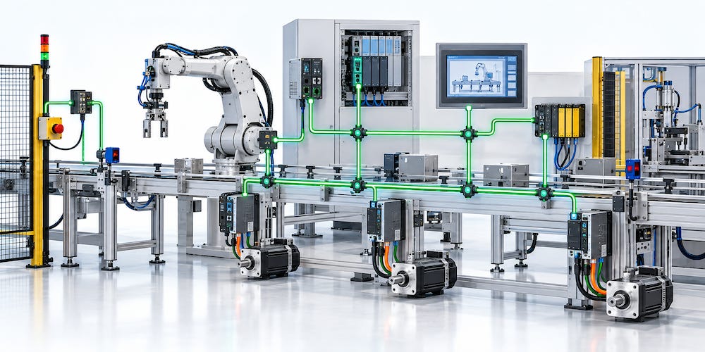
CANopen is a CAN-based higher-layer protocol originally developed for embedded control systems. Today it can be found in a wide range of industrial equipment where multiple controllers, sensors, actuators, drives, and other intelligent devices must communicate reliably over a common network.
Typical CANopen applications include:
Industrial automation
Machine control
Motion-control systems
Motor drives and servo drives
Robotics
Material-handling equipment
Elevators and lifting systems
Medical equipment
Mobile machinery
Sensors and actuators
Embedded control systems
As with J1939 and NMEA 2000, CAN provides the underlying communication technology. CANopen adds the rules required to turn individual CAN nodes into a manageable and interoperable network.
Built on Classical CAN
CANopen traditionally uses Classical CAN and, unlike J1939 and NMEA 2000, primarily uses the 11-bit standard CAN identifier.
The CAN identifier is not arbitrary. CANopen defines a Communication Object Identifier, commonly called the COB-ID, which identifies the type and purpose of a CAN message.
Part of that organization is based on the device’s Node-ID.
A CANopen network supports Node-IDs from 1 through 127, allowing as many as 127 addressable nodes on a network. Node-ID 0 has a special purpose and is not assigned to a normal CANopen device.
CANopen supports several CAN bit rates, traditionally ranging from relatively slow networks up to 1 Mbit/sec, allowing the network configuration to be adapted to cable length and application requirements.
The Object Dictionary
Perhaps the most important concept in CANopen is the Object Dictionary.
The Object Dictionary is a structured collection of all communication parameters, configuration values, device information, and application data that a CANopen device makes available through the network.
Entries are identified using a 16-bit index and, where necessary, an 8-bit subindex.
Rather than simply defining a collection of CAN messages, CANopen therefore provides a standardized way of describing the data contained within each device.
This is one of the fundamental differences between CANopen and protocols such as J1939.
J1939 communication revolves heavily around Parameter Group Numbers and standardized parameters. CANopen revolves around devices and their Object Dictionaries.
Once the Object Dictionary is understood, much of the rest of CANopen begins to fall into place.
PDOs: Real-Time Process Data
For efficient real-time communication, CANopen uses Process Data Objects, or PDOs.
PDOs are designed to transfer process data quickly and with very little protocol overhead.
A motor drive, for example, might transmit its actual speed and status through a PDO, while another PDO could provide the drive with a requested speed or control command.
PDO communication follows primarily a producer/consumer model.
A node produces a PDO and places it onto the CAN network. Any nodes interested in that information can receive it.
PDOs can be transmitted in several ways, including periodically, in response to events, or synchronized with other devices.
Because PDOs are intended for real-time process communication, they do not carry the Object Dictionary index and subindex with every transmission. Instead, the relationship between the PDO data and the Object Dictionary is established through PDO configuration and mapping.
This keeps communication efficient.
SDOs: Accessing the Object Dictionary
CANopen also needs a mechanism for directly reading and writing Object Dictionary entries.
That mechanism is the Service Data Object, or SDO.
Unlike PDOs, SDO communication follows a client/server model.
An SDO client requests access to an Object Dictionary entry in an SDO server. This allows configuration parameters, device information, calibration values, and other data to be read or modified.
For example, a configuration tool might use SDO communication to read a manufacturer’s device name, change an operating parameter, or configure how a PDO is mapped.
PDOs and SDOs therefore serve very different purposes:
PDOs provide efficient real-time process communication.
SDOs provide structured access to the device’s Object Dictionary.
Together they form much of the foundation of CANopen communication.
Network Management
Network management is another area where CANopen differs noticeably from J1939 and NMEA 2000.
CANopen defines Network Management, or NMT, which controls the communication state of CANopen devices.
A CANopen device progresses through defined NMT states such as:
Initialization
Pre-operational
Operational
Stopped
An NMT manager can instruct devices to enter particular states, restart communication, or reset themselves.
For example, a device may remain Pre-operational while its configuration is being established. Once configuration is complete, the NMT manager can place it into the Operational state, where normal PDO communication can begin.
This introduces a more centralized network-management structure than we saw with J1939 and NMEA 2000.
Those protocols rely heavily on distributed address claiming and do not require a central network master. CANopen NMT, by comparison, provides a defined manager/controller relationship for controlling device states.
However, describing the entire CANopen protocol simply as master/slave would be misleading.
CANopen uses several communication models simultaneously. NMT provides centralized state management, PDO communication follows a producer/consumer model, and SDO communication follows a client/server model.
The architecture depends on the type of communication being performed.
Node Monitoring
A network-management system also needs to know whether devices are still operating.
CANopen provides mechanisms for monitoring nodes, with Heartbeat communication being the commonly used method.
A CANopen device can periodically transmit a Heartbeat message indicating its current NMT state.
Other devices configured as Heartbeat consumers monitor these messages. If an expected Heartbeat fails to arrive within the configured time, the consumer can determine that the device may no longer be available.
This allows CANopen systems to detect communication failures without requiring continuous polling of every device.
Emergency Messages
CANopen also defines Emergency Objects, commonly called EMCY messages.
An EMCY message allows a device to report an internal error or abnormal condition immediately.
A drive might report an overtemperature condition, for example, while another device could report a sensor failure or internal hardware error.
Because CAN arbitration gives higher-priority messages preferential access to the bus, emergency communication can be assigned an appropriate priority for rapid transmission.
This provides CANopen with a standardized mechanism for communicating important device faults across the network.
Synchronizing Devices
Many industrial applications require multiple devices to perform actions at coordinated times.
CANopen provides the SYNC object for this purpose.
A synchronization producer periodically transmits a SYNC message. Devices configured to respond to it can then coordinate PDO transmission or internal processing around that common synchronization event.
This is particularly useful in motion-control and machine-control applications where several axes or devices must operate in a coordinated manner.
CANopen also defines additional communication objects and services for other specialized purposes.
Standardized Device Profiles
One of CANopen’s major strengths is that the standardization does not stop at basic communication.
CANopen defines device profiles for different categories of equipment.
A device profile can specify how a particular class of device should organize its Object Dictionary and how common functions should behave.
For example, standardized profiles exist for devices such as drives and motion controllers, encoders, and other types of industrial equipment.
This makes interoperability considerably more practical.
Two devices from different manufacturers may have very different internal hardware and software implementations, but if they conform to the same CANopen device profile, the network interface can present a standardized structure to the application.
What About CAN FD?
Like J1939, CANopen has evolved beyond Classical CAN.
CANopen FD extends the CANopen communication concepts to CAN FD, taking advantage of CAN FD’s larger payload of up to 64 data bytes and its ability to use a higher bit rate during the data phase.
This provides significantly greater bandwidth while retaining many of the fundamental concepts familiar to CANopen developers.
CANopen FD should nevertheless be considered a distinct evolution of the technology rather than assuming that an existing Classical CANopen network can simply be switched to CAN FD.
Devices and protocol implementations must specifically support CANopen FD.
This development also demonstrates the different directions taken by the three higher-layer protocols discussed in this series.
SAE J1939 has incorporated CAN FD through J1939-22. CANopen has evolved into CANopen FD. NMEA, on the other hand, chose Ethernet-based OneNet rather than CAN FD as its path toward substantially higher network bandwidth.
A Different Philosophy
CANopen demonstrates how differently a higher-layer protocol can use the same CAN technology.
SAE J1939 and NMEA 2000 rely heavily on PGNs, source addresses, address claiming, and distributed network operation.
CANopen takes a different approach.
It organizes device data through the Object Dictionary, uses PDOs for real-time process communication, SDOs for structured client/server access, NMT for network-state management, Heartbeat messages for node supervision, and standardized device profiles for interoperability.
Underneath all of this remains the same CAN technology: message arbitration, error detection, retransmission, and robust differential signaling.
But the higher-layer protocol creates a very different type of network.
That is precisely why CANopen, SAE J1939, and NMEA 2000 provide such useful examples of what a CAN higher-layer protocol actually does.
They share the same basic communication technology, yet each has developed a network architecture suited to a very different application environment.
CANopen
CAN identifier: Primarily 11-bit CAN identifiers
Bit rates: Multiple standardized rates, traditionally from 10 kbit/s up to 1 Mbit/s
Maximum nodes: 127 node IDs based on the 7-bit Node-ID field
Network structure: Master/Slave for Network Management (NMT); other communication uses producer/consumer and client/server models
Node addressing: Node IDs 1–127
Network management: NMT state machine with Initialization, Pre-operational, Operational, and Stopped states
Device organization: Object Dictionary provides the central standardized interface to device data and configuration
Real-time data: Process Data Objects (PDOs)
Configuration/data access: Service Data Objects (SDOs)
Node supervision: Heartbeat and error-control mechanisms
Additional services: SYNC, EMCY, TIME, and standardized device/application profiles
Typical applications: Industrial automation, motion control, robotics, machinery, drives, and embedded control systems
Follow CAN Bus Embedded Development
New chapters and technical material are added regularly. Subscribe to receive new additions as the online book continues to grow.