


This article is part of CAN Bus Embedded Development, my growing online book about practical CAN Bus hardware, software, and embedded system development.
View the complete Table of Contents →
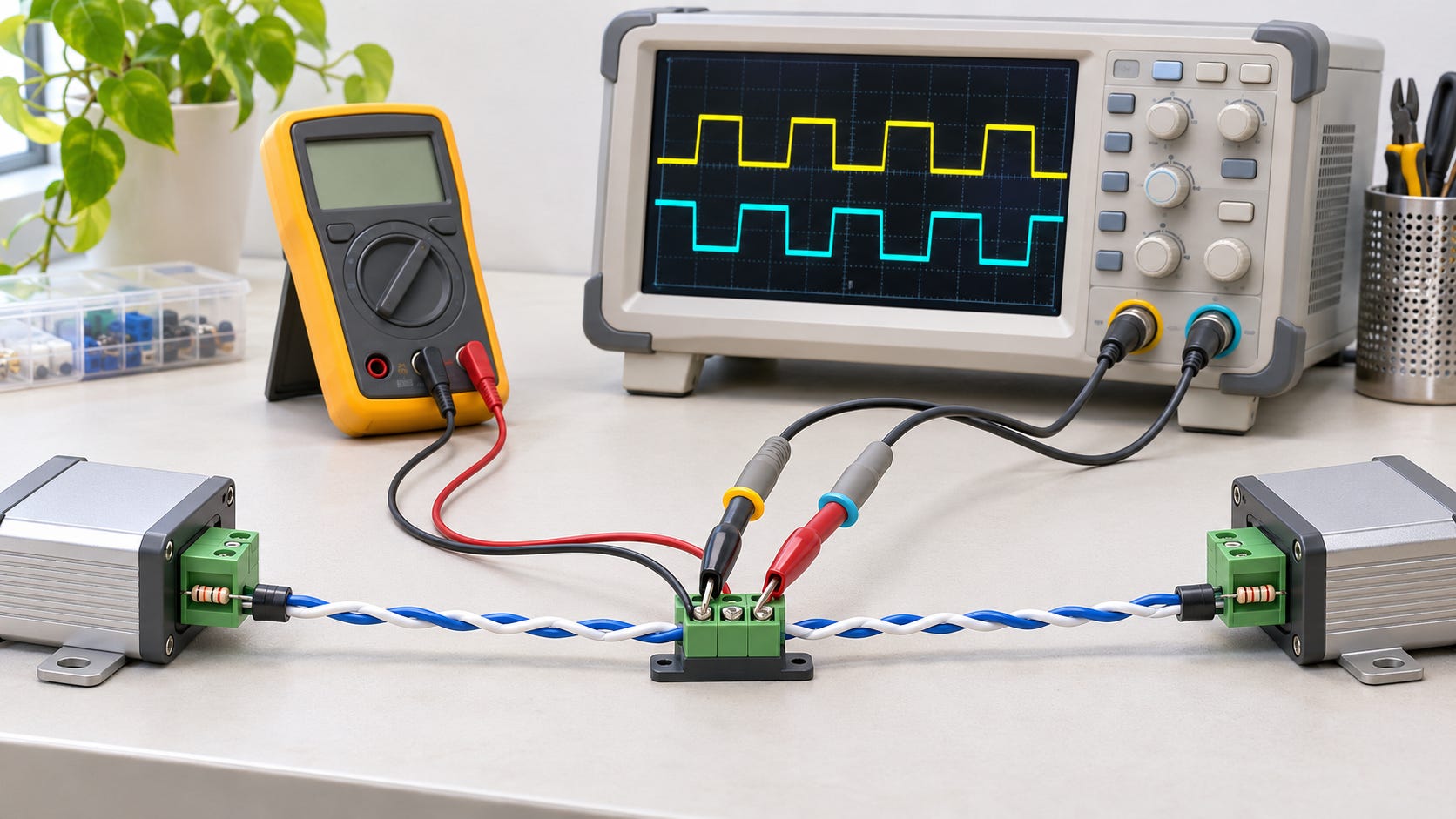
This post covers the most effective ways to diagnose and resolve CAN bus hardware problems.
Checking the wiring
Measure termination resistors
Check CAN_H, CAN_L signal voltages
Test the CAN transceiver
Start with the wiring
Before reaching for a multimeter, trace the CAN wiring from one end of the network to the other. Verify the connector pinouts and make sure CAN_H and CAN_L connect to the corresponding pins at each device. Pay particular attention to harness repairs, adapters, and recently replaced equipment. A swapped pair can prevent one device from communicating even when the resistance measured across the backbone is exactly 60 Ω.
Look for loose connectors, backed-out pins, corrosion, poor crimps, and damaged cable. If communication drops out when the machine vibrates or a connector moves, start there. With the power off and the suspect cable section disconnected, check each conductor for continuity. Gently flex the cable during the test to see whether the connection opens intermittently.
Identify the two physical ends of the backbone and follow the branches to individual devices. Check for unexpectedly long branches and verify that the cable uses a twisted pair intended for CAN. Keep the pair twisted close to each connector. If the installation specifies a CAN ground or reference conductor, check its continuity as well.
Check cable routing and shield grounding
If communication errors coincide with a motor starting, a variable-frequency drive changing speed, or a solenoid-operated valve switching, follow the CAN cable near that equipment. Look for sections where it runs alongside motor leads, drive outputs, or solenoid wiring. Separate the CAN cable from those conductors where practical. Where the cables must cross, aim for a right-angle crossing.
In an electrically noisy environment, shielded twisted-pair CAN cable can help. Follow the equipment manufacturer’s instructions for bonding the shield. The correct arrangement depends on how the equipment and enclosure are grounded.
If the installation specifies a single shield grounding point, you can check for an unintended second connection. With the system powered down, disconnect the shield at its designated grounding point and measure resistance between the shield and ground. A reading above 1 MΩ is expected for this check. If the resistance is lower, look for another path to ground through a connector shell, a cable clamp, or a second shield bond. Reconnect the shield at its designated grounding point after the test.
