


This article is part of CAN Bus Embedded Development, my growing online book about practical CAN Bus hardware, software, and embedded system development.
View the complete Table of Contents →
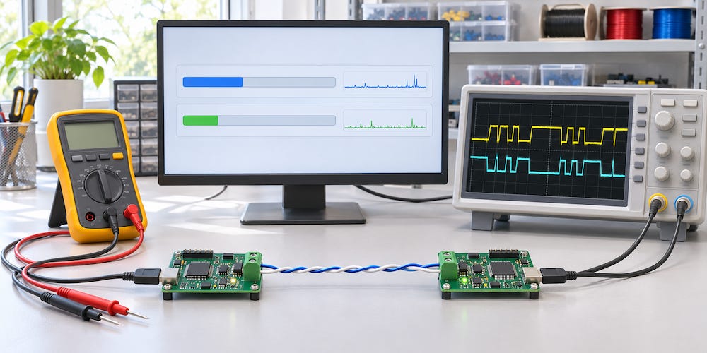
In my experience, sound network design, good wiring, and proper termination prevent about 99 percent of the CAN Bus problems you’re likely to run into. That’s my rule of thumb from working with CAN. When a network starts acting up, I still begin with the basics, even when the symptoms make the problem look more complicated than it is.
By good wiring, I mean more than choosing the right cable. I also mean knowing where the main bus runs, how the nodes connect to it, and where the terminators are installed. Those details are easy to keep track of when you have two boards on a workbench. They’re easier to lose track of when a harness runs through a machine or when someone adds another device after the system has been installed. At that point, it helps to know how the network is actually wired today. The original drawing may describe a simpler system.
Start with what you know
Before I start measuring anything, I want to know what changed and when the problem occurs. Has the network ever worked? Did the trouble start after a device was replaced or a cable was extended? Does communication fail as soon as the system powers up, or only when the machine is running? Does one node disappear, or do several devices lose communication at the same time?
Those questions help me decide where to start. If the trouble began immediately after a new device was added, I’d start with that connection and find out what changed. If the network works while the machine is idle and fails only during operation, I want to know what else happens at the same moment. A drive may be switching on, or part of the machine may be moving and flexing a cable. Either observation gives me a condition I can try to reproduce.
This is where a large or complex network differs from a small bench setup. There may be more cable, more connectors, and more places where a fault can develop. Vibration, moisture, and electrical noise can make the symptoms intermittent. A machine can run for hours before a fault appears and then communicate normally again by the time someone comes to look at it. In that situation, knowing when the problem occurs can be as valuable as knowing which node reported it.
Three ways to narrow the search
Over the next three posts, I’ll cover the checks I consider most useful, in the order I’d normally use them.
Checking termination resistance an wiring
Reading and interpreting CAN controller error counters
Using an oscilloscope
Checking termination resistance is the first measurement I’ll cover. It’s quick, it requires only a multimeter, and it can reveal a problem with the termination or a wiring break that has left part of the bus disconnected. I also check the wiring itself. Even when the resistance is what I expect, I look for loose connectors, damaged cables, and poor connections. Depending on the symptoms, I’ll also check how the cable is routed and how long the branches are.
Reading the CAN controller’s error counters gives me a view of the network while it’s running. I’m interested in whether errors accumulate during transmission or reception, which nodes report them, and what the system is doing at the time. If the counters climb every time a particular operation runs, I have a repeatable condition to investigate. The counters tell me how the controller is reacting. I still have to work out what is making it react that way.
Using an oscilloscope shows what is happening electrically on the bus. At the affected node, it can reveal a brief disturbance, ringing after an edge, or a signal that takes too long to settle. That can help when I have a specific question about what the receiver is seeing at the moment communication fails.
I’ve never been a fan of using an oscilloscope for routine CAN troubleshooting. I find it too involved and time-consuming as a starting point. You have to decide where to probe, set up the measurement, capture the event, and interpret the waveform. With an intermittent fault, you may spend most of your time waiting for it to happen again. I can usually make more progress by checking the installation and looking at what the controllers report. I see the scope as a tool I’d reach for when those checks give me a specific electrical question to answer.
Change one thing at a time
It’s tempting to reseat a connector, swap a cable, and restart the system in one go. If communication comes back, you’ve got the machine running again, but you still don’t know which action made the difference. Whenever I can reproduce the problem, I prefer to make one change and try again under the same conditions. That matters especially with an intermittent fault, where a few minutes of normal operation may simply mean the fault hasn’t shown up again yet.
In the next post, I’ll start with termination resistance. We’ll look at what the reading tells you, what an unexpected reading can point to, and why a normal reading is only one piece of the diagnosis.

Advanced Automotive Fault Diagnosis: Automotive Technology: Vehicle Maintenance and Repair
Develop the fault-finding skills you need for Level 3 and Level 4 vehicle diagnostics courses from IMI, City & Guilds, and BTEC, as well as for ASE, AUR, and other advanced qualifications.
The fifth edition of Advanced Automotive Fault Diagnosis includes 25 new real-world case studies that show how diagnostic principles are applied in the workshop. It explains how vehicle systems and components work and covers the tools and techniques technicians use to identify faults and carry out effective repairs. Updated coverage includes VCDS, decade boxes, diagnostic scanners, pass-through interfaces, sensor simulators, breakout boxes, and multimeters for high-voltage systems.
As vehicle systems grow more complex, technicians need to know how to choose the right test and interpret the results. Definitions, key facts, and “Safety First” notes throughout the book help students build that understanding. Experienced technicians can use it to refine their diagnostic methods and keep up with developments in tools and repair practices. More information…