


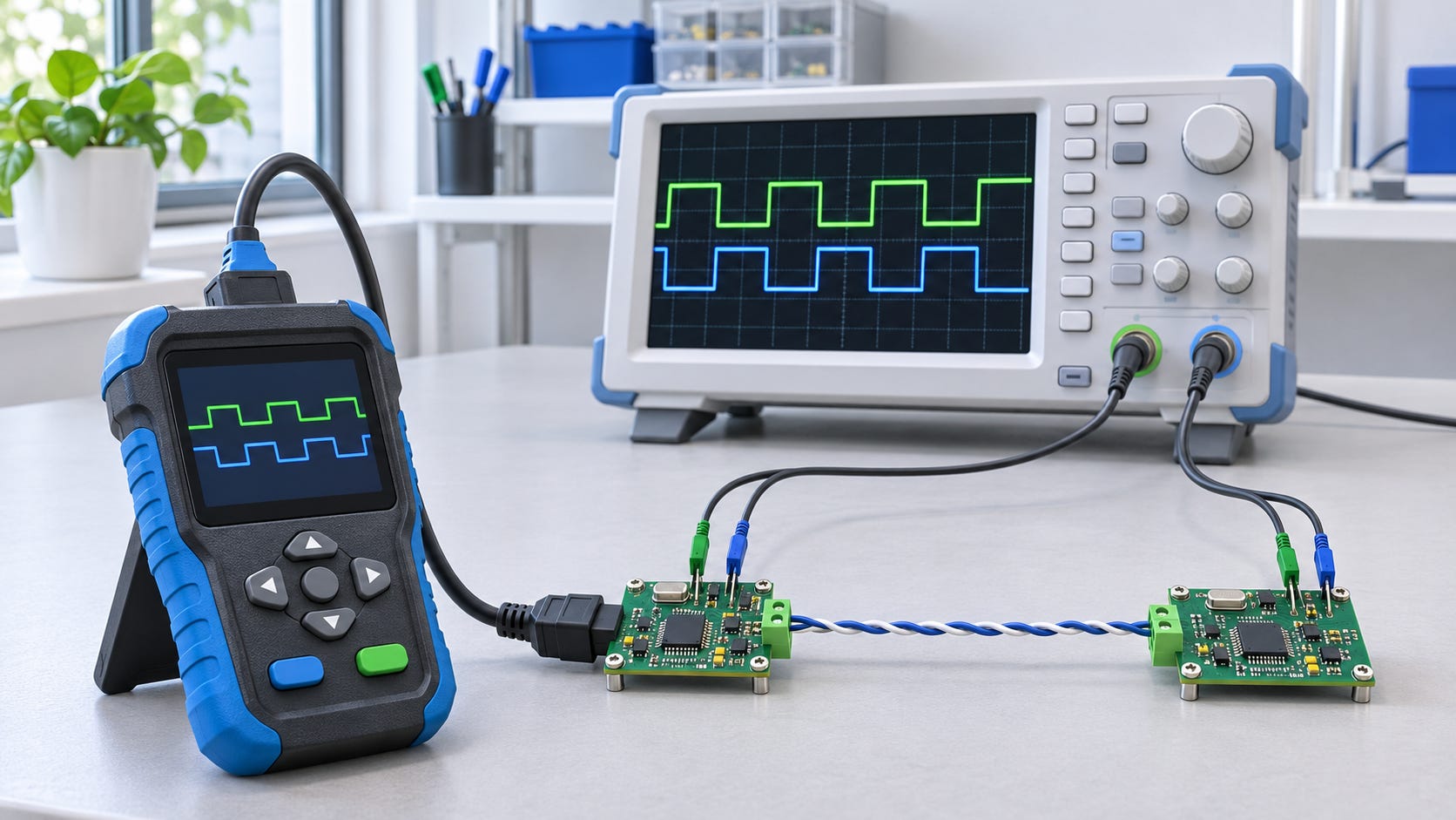
A CAN bus can measure 60 Ω across CAN_H and CAN_L and still lose communication every time a motor starts. Another network can have clean signals while a controller waits for a frame that never arrives. Both problems can look like a CAN communication failure, but they call for different tests.
The term CAN bus tester covers several kinds of equipment. A handheld tester can check termination, voltage, and bit rate in the field. An oscilloscope can show a brief disturbance on the signal lines. A protocol analyzer can reveal a missing frame, and a standalone logger can record what happened just before a machine stopped. Some products combine several of these functions.
What can you test on a CAN bus?
Wiring and termination. Start by inspecting connectors, cable routing, and the location of the terminators. On a conventional high-speed CAN network with one 120 Ω terminator at each end, you should measure approximately 60 Ω between CAN_H and CAN_L with the network powered down. A reading near 120 Ω can indicate a missing terminator or a wiring break that has isolated one end of the bus. A reading well below 60 Ω can point to extra termination or a short. A correct reading confirms the resistance seen at the measurement point. Signal quality requires a separate test.
Signal quality. An oscilloscope shows what happens to CAN_H and CAN_L while the network is operating. Ringing, distorted edges, and brief voltage disturbances give you clues about cable layout, connections, grounding, or electrical interference. A scope with CAN decoding lets you line up a disturbance with the frame being transmitted. Probe location matters. If a particular node keeps dropping off the network, check the waveform at that node’s connector.
Frame traffic and timing. A protocol analyzer shows which identifiers are present, how often frames arrive, and how their payloads change. Use it to investigate a missing periodic frame, a delayed response, or traffic that appears only under certain operating conditions. Error frames can help establish when communication began to fail. You may need a waveform capture or additional measurements to determine the cause.
Intermittent faults. A triggered logger is useful when a machine runs for hours before a problem occurs. It can help establish whether a periodic frame stopped arriving before a shutdown, whether error frames appeared at the same time, or whether the traffic changed when another device switched on. That sequence gives you a starting point for reproducing the fault.
Response to deliberate faults. A disturbance interface can interfere with selected bits in a CAN frame under controlled conditions. On a development bench, this makes it possible to repeat the same fault and observe how a controller detects the error and resumes communication.
PEAK-System PCAN-MiniDiag FD
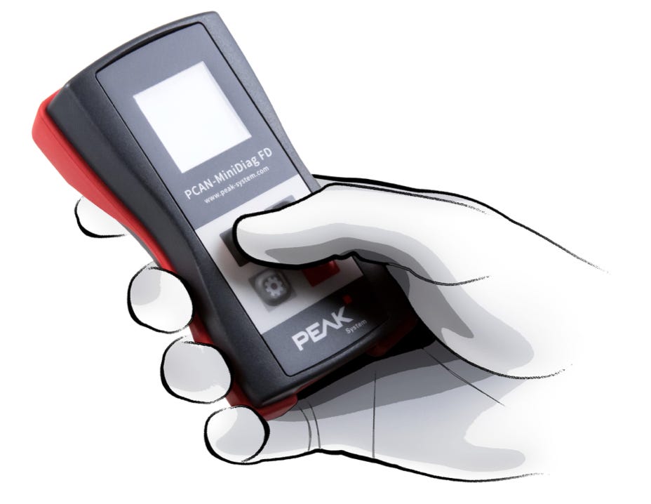
The PCAN-MiniDiag FD is a compact handheld tester for Classical CAN and CAN FD. It measures termination resistance, CAN line voltages, and bus load. It can also detect the bit rate of an active network. Its main use is a quick field check when you need to verify basic network conditions before bringing out a scope or connecting a computer.
PEAK-System PCAN-MiniDiag FD user manual
PEAK-System PCAN-Diag FD
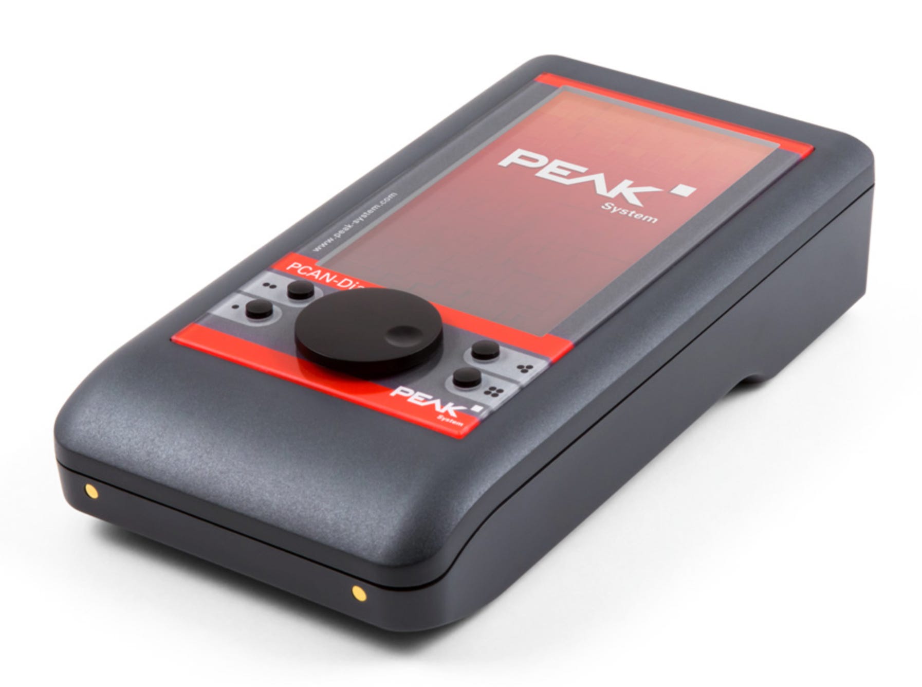
The PCAN-Diag FD combines electrical measurements, an oscilloscope, and a traffic display in a handheld instrument. It samples CAN_H and CAN_L on separate channels and can decode frames from the captured waveform. That makes it useful when you need to check both the electrical signal and the traffic at the same connection point.
PEAK-System PCAN-Diag FD product page
GEMAC CAN-Bus Tester GT3
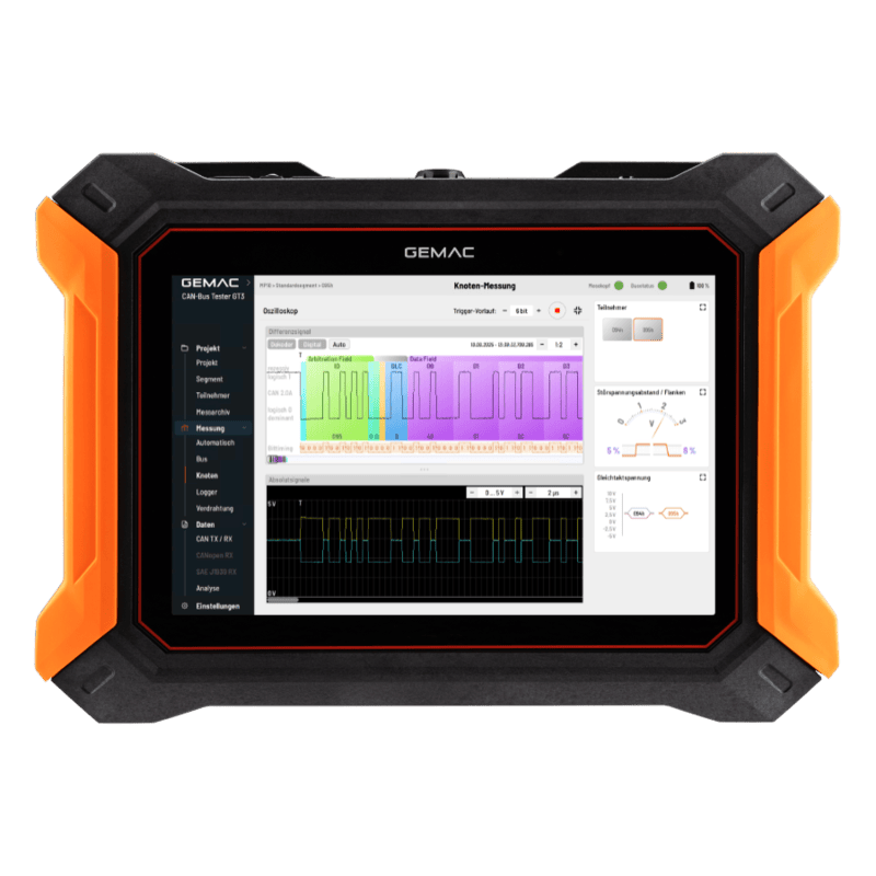
The GT3 combines wiring tests, cable-length measurement, oscilloscope functions, and protocol monitoring. It is aimed at commissioning and troubleshooting installed CAN networks where the investigation may move from checking the cable to inspecting waveforms and error frames. GEMAC identifies the GT3 as the successor to its discontinued CAN-Bus Tester 2.
GEMAC CAN-Bus Tester GT3 documentation
Pico Technology PicoScope
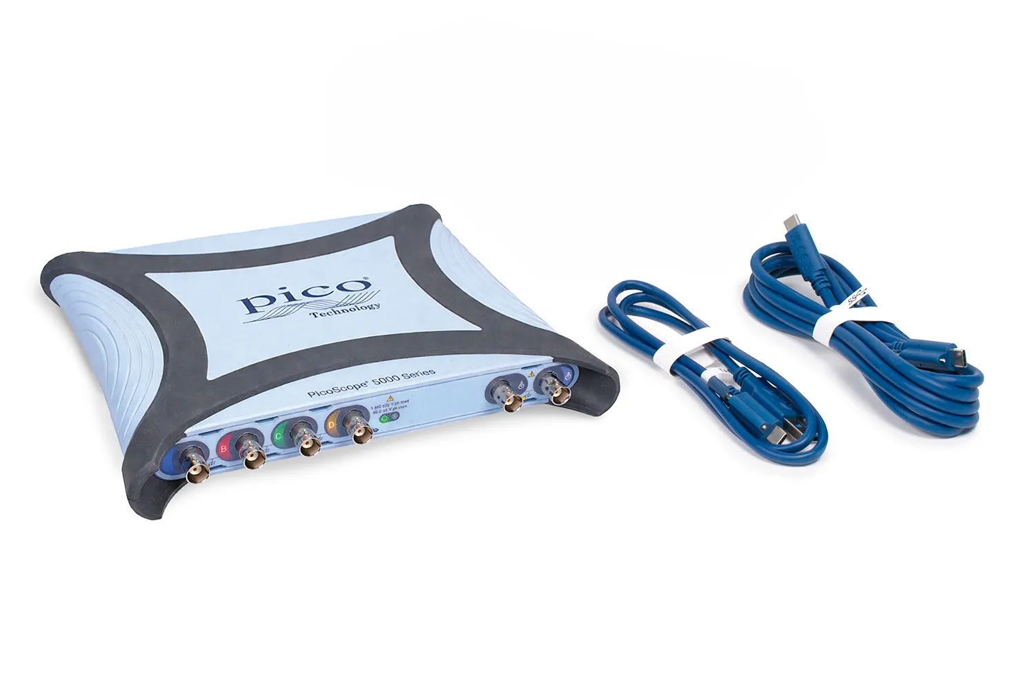
PicoScope oscilloscopes with CAN and CAN FD decoding display decoded frame information alongside the electrical waveform. This is useful when you need to inspect ringing, noise, or a distorted edge and see exactly where it occurs within a frame. The scope also lets you compare measurements at different points on the network when a fault affects only part of the installation.
Pico Technology serial decoding guide
Kvaser Memorator Pro 2xHS v2
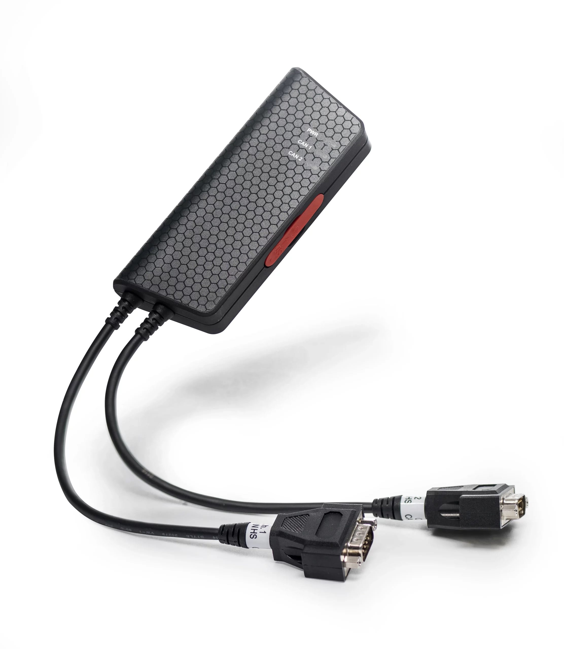
The Memorator Pro 2xHS v2 is a two-channel CAN and CAN FD interface that also works as a standalone logger. It supports message filters, triggers, error detection, and SD-card storage. Its standalone operation is useful when a fault occurs during a long production run or under conditions where keeping a computer connected is impractical.
Kvaser Memorator Pro 2xHS v2 product page
Vector VH6501
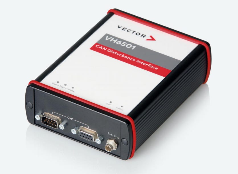
The VH6501 is a CAN and CAN FD interface designed for controlled bus disturbances. It can interfere with specific parts of a frame so that developers can observe how a device detects and handles communication errors. Its primary role is bench validation, where the same disturbance needs to be reproduced across multiple test runs.
Vector VH6501 technical documentation