


This article is part of CAN Bus Embedded Development, my growing online book about practical CAN Bus hardware, software, and embedded system development.
View the complete Table of Contents →
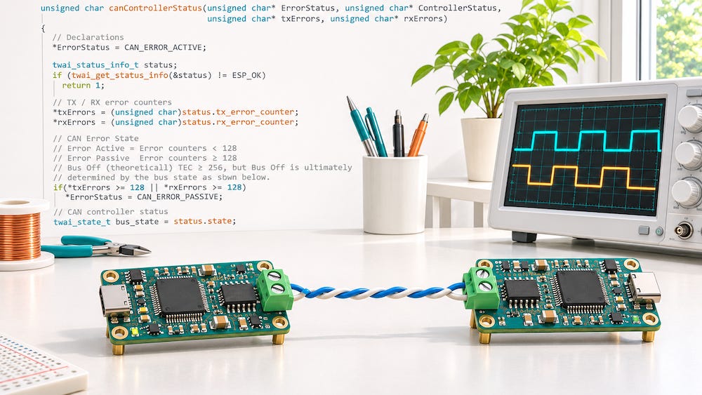
In this post, I’d like to look at what goes into designing a CAN Bus driver for an embedded system. I often start with a code example when working with an unfamiliar controller, but once I can send and receive frames on the bench, I still have a few questions. Can the driver keep up with the 20-frame burst used in J1939 testing? Can I tell when a receive buffer overflows or the controller goes bus-off? And can I put the controller into silent mode to monitor an existing network without affecting its traffic? These are the kinds of requirements I consider when choosing a driver or writing my own.
GitHub offers a wealth of CAN Bus examples for Arduino boards, ESP32 and STM32 devices, and other ARM Cortex-based platforms. I appreciate the developers who share that code. A good example can save me hours of work, especially when I am bringing up an unfamiliar CAN controller. But a sample that sends and receives a few frames on the bench has demonstrated only a small part of what I need from a driver.
Readability matters as much as functionality when I decide whether to use someone else’s code. I want to see where a received frame goes, how the transmit queue is serviced, and what happens when the controller reports an error. If I have to trace register operations scattered throughout the application just to answer those questions, much of the time I hoped to save is already gone.
What does a successful write mean?
The basic driver functions are straightforward. I need to read a frame, write a frame, and check the controller’s status. What deserves more attention is the meaning of the return code. A successful write may mean that the driver accepted a frame into its software queue. The frame could still be waiting for a hardware transmit buffer or for its turn on the bus. If the application needs to know whether the controller actually transmitted it, the driver should report transmit completion separately.
The same principle applies on the receive side. An empty queue is a normal condition. A receive overrun means that frames were lost. A driver that reports both conditions with the same generic error makes it unnecessarily difficult to diagnose missing data.
Size the buffers for bursts
Average bus load can be misleading when sizing receive buffers. One test I use for a J1939 application is a burst of 20 back-to-back CAN frames at full bus utilization, with only the required interframe spacing. The question is whether the application can capture every frame even when its main loop or receive task is busy doing something else.
I usually put a software ring buffer behind the controller’s receive FIFO or mailboxes. The receive interrupt moves frames out of the hardware and into the ring buffer, while the application takes them out when it is ready to process them. I keep the interrupt handler short and leave operations such as PGN decoding, display updates, and logging to the application. I also prefer to use transmit interrupts to refill hardware transmit buffers as they become available.
I look for configurable receive and transmit queue depths because the two sides often have different needs. A monitor may have to absorb a substantial receive burst, while a transmitting application may need room to hold frames waiting for arbitration. I size the receive queue for the longest period the application can go without draining it, and I make overflow visible through a dropped-frame counter. A larger software queue buys the application time, provided the interrupt handler can still empty the hardware FIFO before it overruns.
Make controller errors visible
I want a driver to expose the receive and transmit error counters, along with the controller’s error-active, error-passive, and bus-off states. These are among the first things I check when a CAN network behaves intermittently. Rising counters can point toward wiring, termination, electrical noise, a bit timing mismatch, or a faulty transceiver. A transmitter can also report errors on a bench simply because there is no active receiver to acknowledge its frames. The counters tell me what the controller is experiencing, which helps narrow down where to look.
Persistent errors affect the rest of the network. When an active error flag disrupts a frame, the failed transmission consumes bus time, and a retry can take up still more. Enough repeated errors can delay otherwise healthy traffic. I prefer a driver that can notify the application when the controller changes error state and expose enough information to diagnose a bus-off event. I also want to know what happens to queued transmissions during bus-off and how the application can bring the controller back online.
Silent mode for passive monitoring
For a device whose only job is to display or record traffic already on the bus, I consider hardware silent mode essential. Also called listen-only mode, it lets the controller receive frames without transmitting data, acknowledging frames, or sending error flags. A passive dashboard or logger can therefore observe an existing network without altering which frames are acknowledged or disrupting traffic if its own bit timing is configured incorrectly.
The distinction matters on the bench. If the setup consists of one transmitter and one silent monitor, the transmitter has no other node to acknowledge its frames. It can report acknowledgment errors even though the monitor can see the traffic. A dashboard that sends requests or participates in J1939 address claiming needs normal mode for those operations. I also check what diagnostics are available in silent mode, since some controllers freeze their error counters while listening.
Sleep mode for power management
Sleep mode addresses a different requirement. A vehicle module may need to draw very little current after the ignition is switched off and resume operation when the vehicle wakes up. Depending on the hardware, that can involve putting the CAN controller into a low-power state and switching the transceiver into standby or sleep. A wake-capable transceiver can detect a qualifying bus wake-up pattern, while some designs also support a local wake input such as an ignition signal.
The driver needs a defined sequence for entering sleep and restoring normal communication. I check what happens to pending transmissions and how long the receiver takes to become ready after wake-up. A bus frame that triggers wake-up may arrive before the controller is ready to capture it. If the application depends on receiving the first message, that behavior needs to be tested on the actual hardware.
When I evaluate a CAN driver, I want to know how it behaves when frames arrive faster than the application can process them, when the controller detects repeated errors, and when the hardware changes operating modes. Those tests tell me how much work remains between the example on GitHub and the driver I can use in a product.