


When choosing a CAN Bus development board, it is tempting to start with processor speed, memory, and the number of CAN ports. Those specifications matter, but I would start with a different question:
What software does your application actually need?
A system that records CAN messages and presents them through a web interface has different requirements from a device that reads a sensor and transmits its value every 20 milliseconds. Both communicate over CAN. Their software development can be quite different.
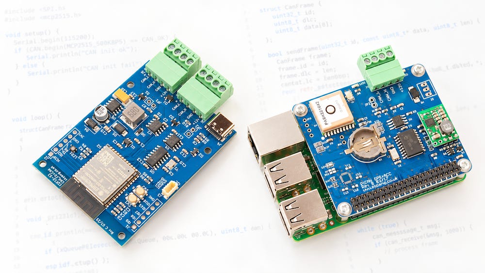
At Copperhill Technologies, we offer platforms for both approaches: Raspberry Pi with PiCAN CAN Bus HATs and microcontroller products such as the ESP32-S3 board with CAN FD and Classical CAN ports. The useful question is which approach makes your particular project easier to develop and maintain.
First, a Small Correction About “No Operating System”
Microcontroller development is often described as programming “without an operating system.” That description fits a bare-metal application, but it needs some qualification when we talk about the ESP32.
Espressif’s ESP-IDF development framework includes FreeRTOS, a real-time operating system. Arduino development on the ESP32 also commonly runs on top of that framework. You may write a familiar setup() and loop(), but that does not mean the processor is running without an operating system underneath.
For this discussion, the distinction is between an application running under a general-purpose operating system such as Linux and firmware running on a microcontroller, possibly with an RTOS.
With Linux, your program runs as a process alongside other programs and system services. With an ESP32, you build the device’s firmware, including your application, its libraries, and the supporting runtime.
Raspberry Pi and PiCAN: Develop Above the Hardware
On a Raspberry Pi running Linux, a compatible PiCAN HAT provides the CAN hardware, while the Linux driver connects it to SocketCAN.
SocketCAN presents CAN interfaces through Linux’s networking infrastructure. Your application uses a socket or a library built on that interface instead of managing the controller’s registers and SPI transactions itself. Multiple applications can access the same CAN interface, which is convenient when you want to monitor traffic while your own program is running.
The PiCAN family includes different models, so check Raspberry Pi compatibility, port count, and Classical CAN versus CAN FD support before selecting a HAT. CAN FD capability is specific to the hardware you choose.
Once the appropriate driver and board configuration are in place, you can test communication before writing your application. For example, with can-utils installed, a Classical CAN interface named can0 can be configured for 500 kbit/s:
sudo ip link set can0 down
sudo ip link set can0 type can bitrate 500000
sudo ip link set can0 up
candump can0
In another terminal, you can transmit a test frame:
cansend can0 123#01020304Use these settings only on a suitable test network whose bitrate and message definitions you control. These commands do not replace the HAT’s installation instructions, and CAN FD needs additional configuration.
The practical advantage is that you can establish whether the interface communicates before adding decoding, file storage, or a user interface.
Where Linux Makes the Work Easier
Consider a CAN data logger. Receiving frames is only the beginning. You may also need file rotation, timestamps, remote access, configuration files, a database, and a browser-based display.
Linux gives you an established environment for those functions. You can develop in C or C++, or use Python with a suitable CAN library. You can update the application separately from the operating system and arrange for a service manager to start it automatically.
For this type of project, Raspberry Pi with a suitable PiCAN HAT is a sensible starting point. It lets you spend more development time on the information you want to collect and present.
However, the operating system does not design a reliable application for you.
If your receive loop writes every message directly to a slow disk or waits for an internet connection, traffic may accumulate faster than you process it. I would separate CAN reception from storage and network activity, using a bounded queue and keeping track of dropped messages.
A logger that silently loses data is difficult to trust, regardless of the processor running it.
ESP32: Your Application Becomes the Firmware
With the ESP32, development moves closer to the device itself. You typically write C or C++ using the Arduino environment or ESP-IDF, compile the firmware, and flash it to the board.
Libraries and drivers still do much of the low-level work. You do not have to write a CAN controller driver from scratch. You do, however, make more explicit decisions about initialization, task scheduling, buffers, peripheral access, and recovery.
The ESP32-S3 board offered by Copperhill illustrates an important software distinction. Its Classical CAN connection uses the ESP32-S3’s integrated TWAI controller. Its CAN FD connection uses an external MCP2518FD controller over SPI.
These are different controller interfaces and require the appropriate software for each.
The integrated ESP32-S3 controller does not support CAN FD. Installing a different library cannot change that hardware limitation. To use CAN FD on this board, your code must work with the external MCP2518FD controller through a compatible driver or library.
The product page includes schematics and demonstration code. I would begin with those examples, confirm communication on the port I intend to use, and then add my application one function at a time.
The Firmware Problem: Keep CAN Moving
Imagine an ESP32 device that reads a sensor, sends periodic CAN messages, receives configuration commands, and reports status over Wi-Fi.
A simple loop may work during the first demonstration. Trouble starts when a Wi-Fi operation blocks, a sensor takes longer than expected, or a burst of incoming frames fills the receive buffer.
My approach would be to separate those responsibilities:
Receive CAN frames promptly and place relevant data in a bounded queue.
Process messages outside time-sensitive receive handling.
Schedule periodic transmissions without long blocking delays.
Keep Wi-Fi, display updates, and lengthy logging operations from holding up CAN work.
Record queue overflows, transmission failures, and controller state changes.
With FreeRTOS, tasks and queues can help organize that design. With a simpler application, a carefully written nonblocking loop may be sufficient.
Neither approach makes timing automatic. Priorities, buffer sizes, interrupt handling, and shared resources still need attention.
Timing: CAN Arbitration Is Only Part of the Story
CAN’s arbitration mechanism decides which pending frame gets access to the bus. It does not decide when your software prepares that frame.
That distinction matters when a message is supposed to be transmitted periodically or a received command must trigger an action within a deadline.
A standard Linux application can experience scheduling delays. Microcontroller firmware gives you more direct control over scheduling and peripherals, but it can still miss deadlines because of blocking calls, unsuitable task priorities, or excessive interrupt work.
I would define the timing requirement first, then measure the complete path under realistic load. “Real-time” in a product description is not a substitute for that measurement.
The Protocol Still Belongs in Your Software Design
Sending a CAN frame does not automatically implement SAE J1939, CANopen, or NMEA 2000.
Your software still needs the applicable message definitions and protocol behavior. Depending on the protocol, that may include address claiming, transport of longer messages, network management, and timing rules.
For J1939, for example, receiving a 29-bit identifier is only the beginning. You need to interpret its fields and handle the required behavior of your application.
Choose protocol software that fits both the platform and the intended role. A passive monitor and an active network node have different responsibilities.
Debugging: Use One Platform to Help Develop the Other
There is no reason to choose only one platform for the entire development process.
A Raspberry Pi with a PiCAN HAT can serve as a monitor and test tool while you develop an ESP32 CAN node. You can inspect what the firmware actually transmits, check identifiers and payloads, and compare observed traffic with your intended schedule.
On the ESP32, add useful diagnostics from the start: receive counts, overflow counts, transmission failures, and bus-off status. Make recovery an explicit part of the design.
Also test what happens when traffic stops, the device restarts, or an expected message arrives late. Successfully exchanging one frame proves very little about how the finished device will behave.
Which Approach Would I Choose?
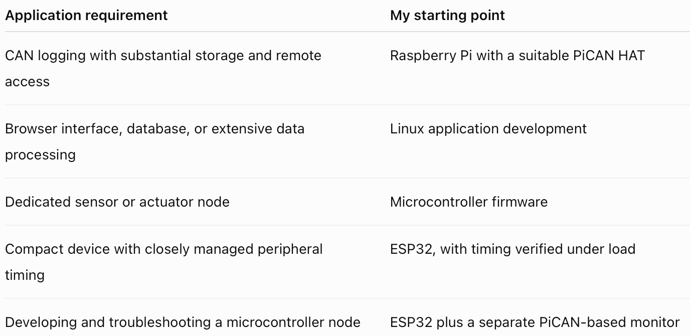
These are starting points. An ESP32 can provide wireless connectivity and a web interface, and Linux can support demanding timing requirements with an appropriate design. The question is how much work each platform creates for your application.
My preference is to choose the simplest software environment that meets the requirements. A full Linux system can save considerable effort when the project needs storage, networking, and user interfaces. A microcontroller can be a better fit when the device has a focused job and needs close control over its operation.
The PiCAN range and the ESP32-S3 CAN FD/Classical CAN board at Copperhill Technologies support both directions.
Before buying the board, write down what the software must do, how quickly it must respond, and how you will test it. That small step often tells you more than a long comparison of processor specifications.